
Heat Shrink
Heat Shrink Tubing
Insulation, sealing, strain relief and terminal protection.
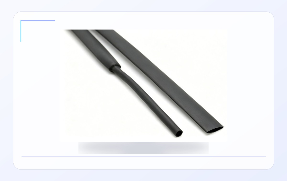 Heat Shrink
Typical technical parameters
- Material
- Heat shrink material by application
- Temperature range
- By selected heat shrink series
- Voltage / insulation
- Electrical insulation and mechanical protection
- Size range
- Shrink ratio 2:1 / 3:1 / 4:1
- Structure
- Heat shrink tubing supplied as spools, lengths or cut pieces
| Size | As supplied ID | After recovery ID | Spool length | Application range |
|---|---|---|---|---|
| 0.5 | 0.80±0.20 | <=0.35 | 400 m | 0.3-0.6 |
| 1.0 | 1.50±0.20 | <=0.65 | 400 m | 0.75-0.9 |
| 5.0 | 5.50±0.20 | <=2.50 | 200 m | 2.6-4.5 |
| 8.0 | 8.50±0.30 | <=4.00 | 100 m | 4.2-7.2 |
| 16 | 16.50±0.40 | <=8.00 | 100 m | 8.3-15 |
| 30 | 31.50±1.00 | <=15.00 | 50 m | 16-29 |
| 100 | >=100 | <=50.00 | 25 m | 55-85 |
| 150 | >=150 | <=75.00 | 25 m | 80-120 |
| Catalog notes | Value |
|---|---|
| Shrink ratio | 2:1 / 3:1 / 4:1 |
| Features | Oil and chemical resistance, halogen-free low smoke RoHS compliance, insulation and heat/voltage resistance |
Note: Values are typical reference ranges. Final specification can be confirmed by sample testing, drawings and customer standards.
Key features
- Electrical insulation, mechanical protection, environmental sealing and strain relief
- High expansion ratio can repair cable jackets without removing connectors
- Clear types allow inspection of covered components
Typical applications
- Back-end connector sealing
- Breakouts and connector-to-cable transitions
- Cable repair and terminal protection